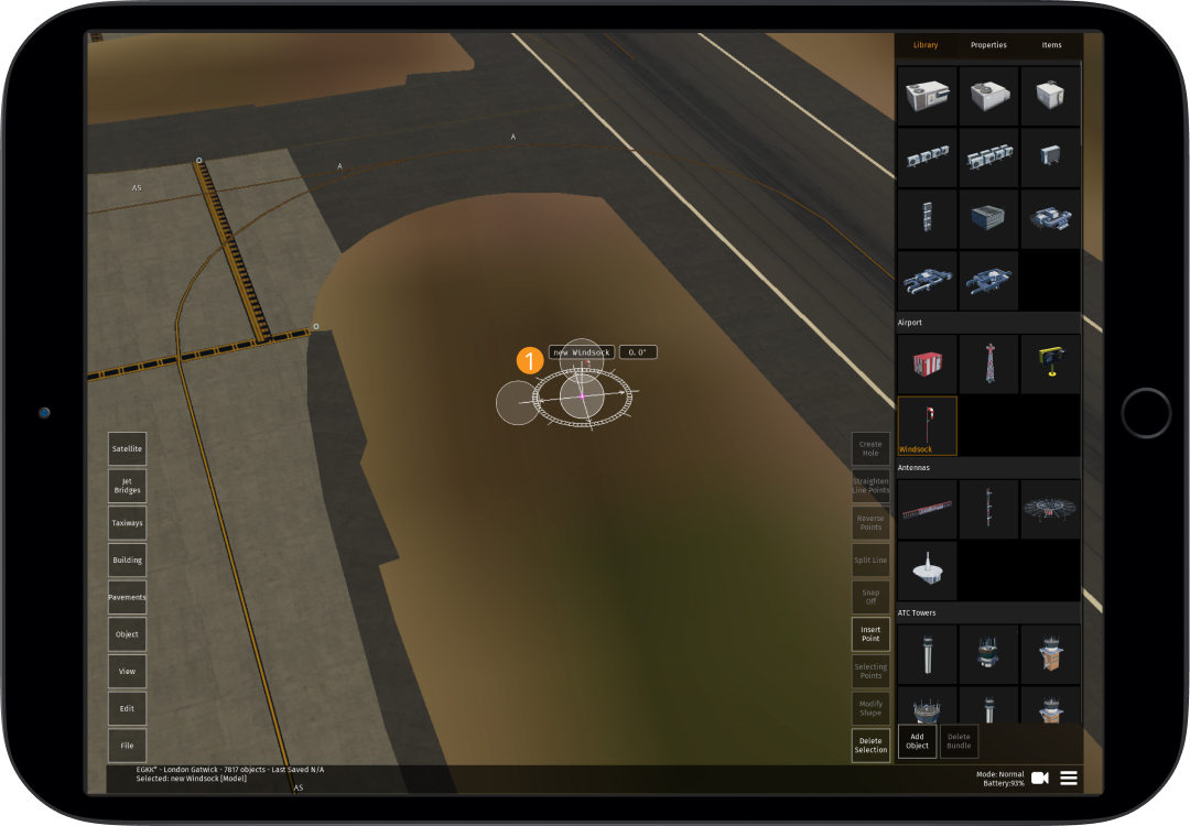
2.1 Editor Screen
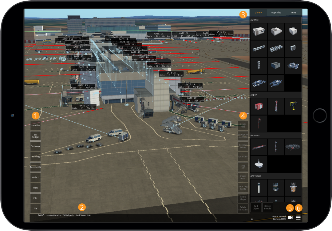
2.1.1
-
The management buttons allow you to manage files, edit recent activity, change the view, adjust object altitude, add/change pavements/taxiways/buildings and import satellite imagery (see 2.1.2 below)
-
"Last saved" information is displayed for the current editing session only. If a new editing session is started (even if you remain in-app), it will reset the "Last Saved" on the bottom bar to "N/A" until the session is saved
-
The main navigation bar contains the library of objects, properties and loaded items (see 2.1.3 below)
-
The edit buttons allow you to move, copy & paste, edit or delete selected buildings, objects and taxiways (see 2.1.4 below)
-
The camera in use can be changed here (see 2.1.5 below)
-
Time, ending current session and adjusting settings can be changed here (more information on settings can be found in the Getting Started Guide)
Management Buttons
2.1.2
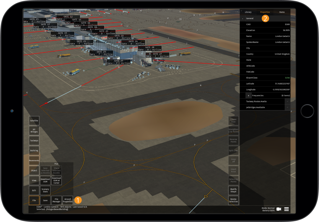
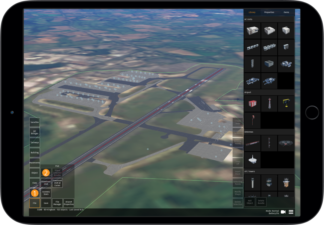
File
| Button | Function |
|---|---|
| Save Selected as Bundle | Select a group of buildings and/or objects and then tap this button to save them as a bundle for future use to speed up editing times |
| Share Selected Bundle | When a bundle is selected from the library, this can be shared with other Editors using this button |
| Download OSM | By tapping this button, the Open Street Map data will be downloaded which will usually provide most of the buildings within (and close to) the airport boundaries |
| Download OSM at Cursor | If buildings are missing or you accidentally delete some, you can download the OSM data at the cursor point with this button (it has an approximate range of 200 meters) |
| Scenery Stats | This shows key stats about the objects currently placed including poly count. It also contains the "Scenery Checker" which will ensure that your airport is compliant with the limits put in place (i.e. performance limitations, objects outside the boundary, naming issues/duplicates of gates etc. - see 12.1.2 below) |
| Save | Saves the latest changes locally to your device. Note: The autosave function will automatically save once every minute to ensure work is not lost |
| File Manager | This will show when it was last modified locally, options for upload, restoring backups and exporting (see table below). Note: Airports will only be uploaded to the server when "upload complete" is shown. Downloading a version from the server will override your local device version |
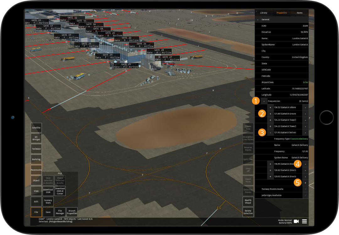
| Airport Properties | General details of the airport can be changed including the ICAO code, elevation, name, airport class and frequencies |
File Manager:
If it is a new airport, after the initial upload you will be assigned the airport to ensure that no one else can override your work at that airport.
| File Manager | What it does |
|---|---|
| Local | Last modified locally (on your device) |
| Online | If changes have been made, this will indicate that the local changes are ready for upload |
| Upload as Draft* | This will save your work online (recommended to do this regularly to have a copy stored online in case there are any app issues causing you to lose your recent edits) - this is also required for peer reviews as other Editors will then be able to view your work so far |
| Upload for Review* | When your airport is complete, you can submit it for an official review |
| Revert to last Upload | If you want to go back to the last upload, this will undo any work done |
| Backups | A backup can be selected by tapping on it (turns amber to show it is selected) and then "Restore" |
| Restore | Will revert to the previous version that is selected within the backup list |
| Delete All Local | The files will autosave at intervals but this can build up and there may be too many local files. This button clears your cache |
| Export | This will export the file from the Scenery Editor and into your chosen location such as a Google Drive (not required) |
| Close | Closes the file manager |
*When uploading a new version of a recently edited airport (i.e tapping "Upload as Draft" or "Upload for Review"), Editors will be required to submit a "changelog" which highlights what has been changed in that version. Changelogs must be specific to ensure that it is clear what has been changed (e.g. "Adjusted C19 jetbridge. Changed taxiway line type on Taxiway A"). Additional details can be added to the IFC airport thread if required (see 12.1 below)
Edit
| Button | Function |
|---|---|
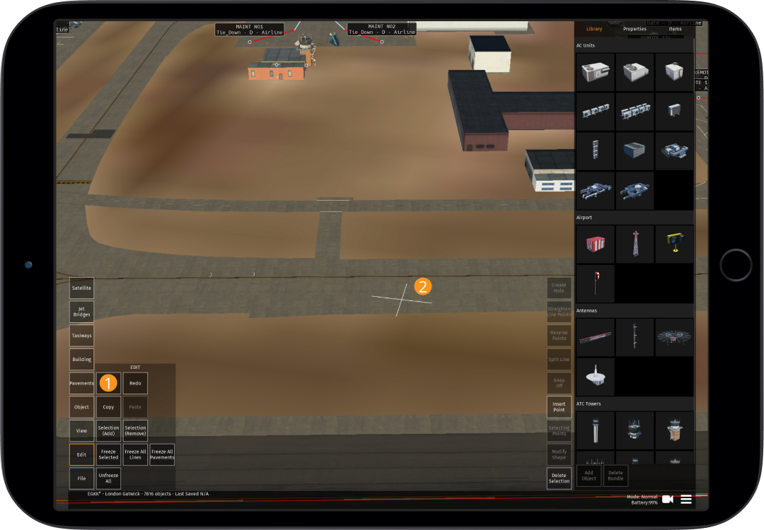
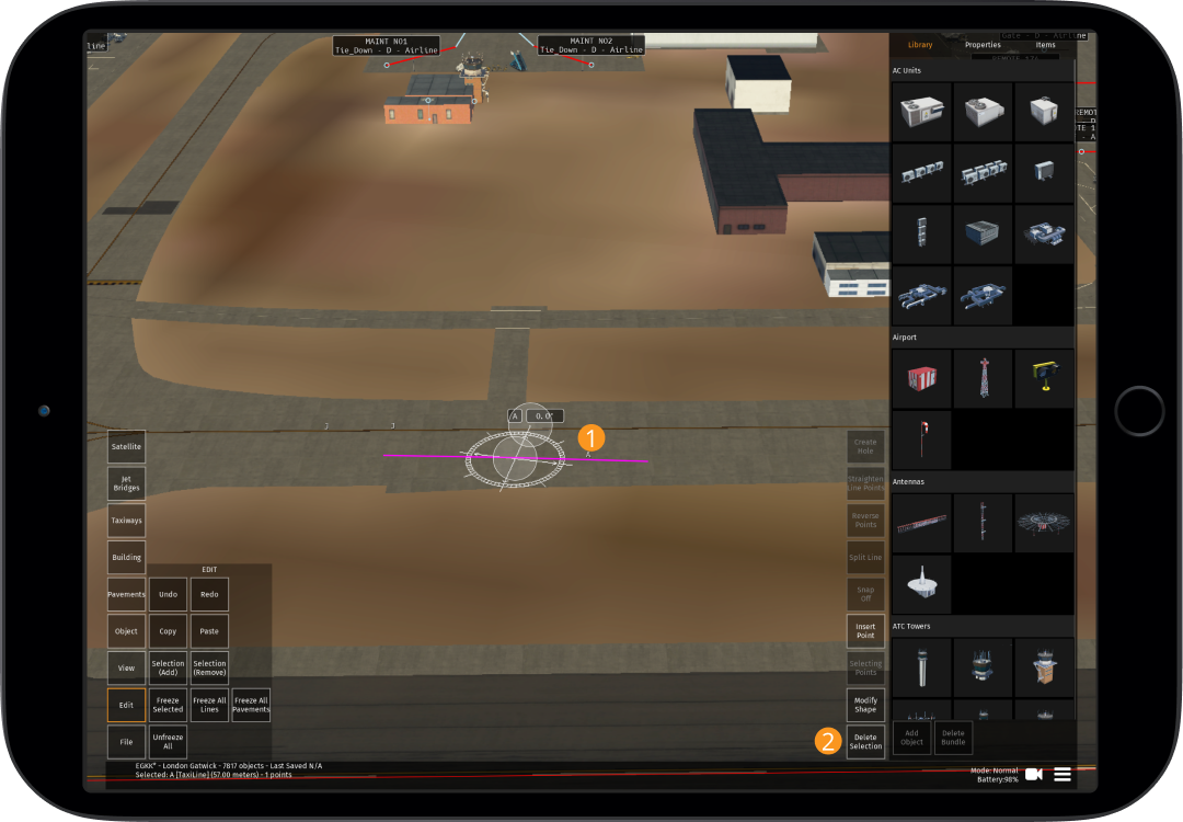
| Undo | Undo your latest edit |
| Redo | Redoes your last "undo" edit |
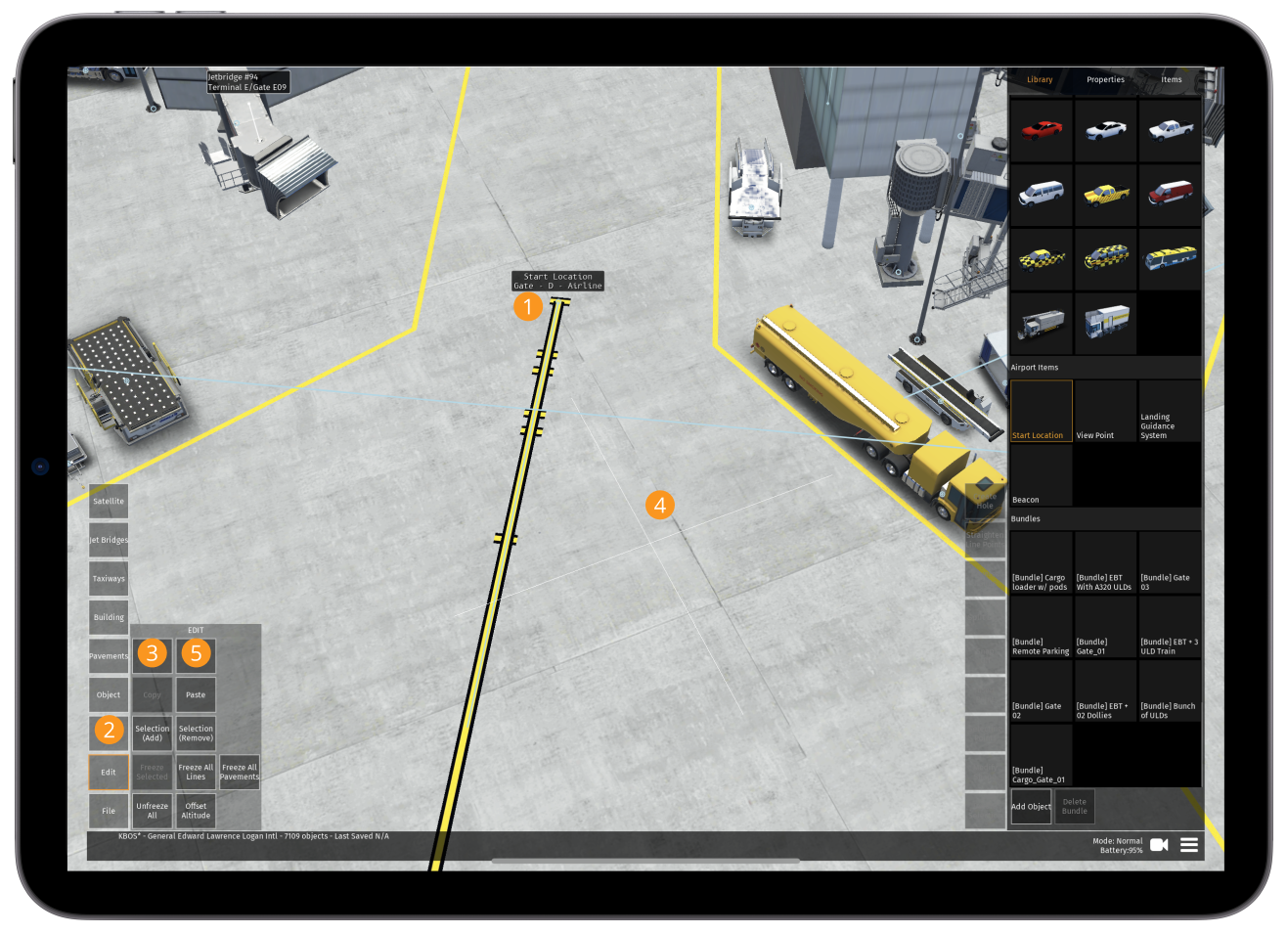
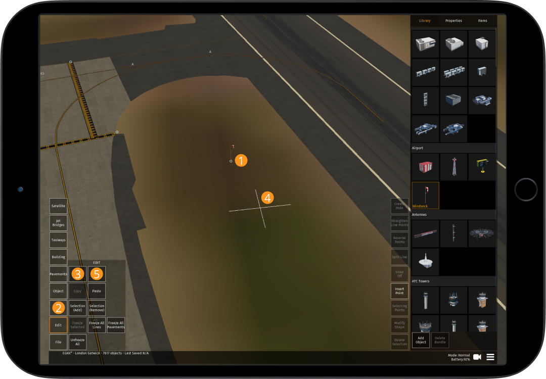
| Copy | Copy the current selection |
| Paste | Paste the selection most recently copied |
| Selection (Add) | Create a selection of several objects to move or edit them as a group. While "Selection (Add)" is active, all objects you select by tapping on them or using the "rectangular selection tool" will be added to the selection |
| Selection (Remove) | Objects that are selected by tapping on them or using the "rectangular selection tool" while the "Selection (Remove)" feature is active are removed from the existing selection |
| Freeze Selected | Freezes selected items so that they cannot be moved or their properties adjusted |
| Freeze All Lines | Freezes all lines so that they cannot be moved or their properties adjusted |
| Freeze All Pavements | Freezes all pavements so that they cannot be moved or their properties adjusted (particularly useful for large pavement areas that you do not want to accidentally move/edit once completed) |
| Freeze All Buildings Objects | Freezes all buildings and objects so that they cannot be moved or their properties adjusted |
| Unfreeze All | Unfreezes all building, pavements, taxiways and/or objects and allows them to be moved and their properties adjusted |
View
| Button | Function |
|---|---|
| Buildings | When displayed in "white" buildings are deselected and not shown. When in "amber" buildings are selected and displayed |
| Models | When displayed in "white" objects are deselected and not shown. When in "amber" objects are selected and displayed |
| Taxiway Lines | When displayed in "white" taxiway lines are deselected and not shown. When in "amber" taxiway lines are selected and displayed |
| Pavements | When in "amber" pavements are selected and displayed. When tapped again, the text will change to "Pavement Outlines", this will then only show pavement outlines. Another tap will change the text back to "Pavements" and the color to "white", this will deselect them and they will not be shown |
| Runways | When displayed in "white" runways are deselected and not shown. When in "amber" runways are selected and displayed |
| Taxiway Network | When displayed in "white" the taxiway network is deselected and not shown. When in "amber" the taxiway network is selected and displayed (only when built by the "Build Taxiway Layout") |
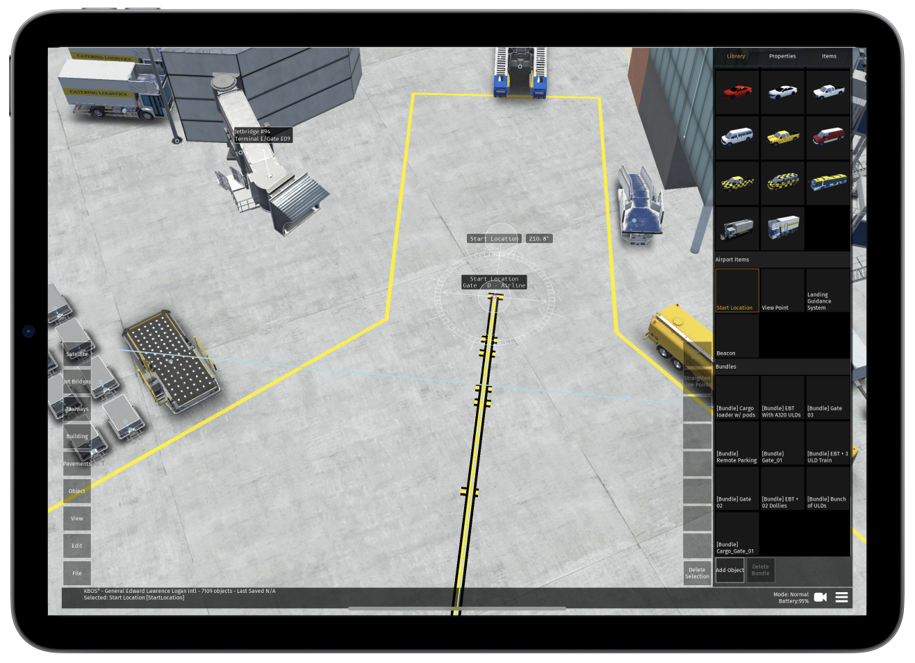
| Start Locations | Shows all locations that aircraft are able to spawn in-app when in "amber". When in "white" these are deselected and not shown |
| Satellite Background | When displayed in "white" the satellite background is deselected and not shown. When in "amber" the satellite background is selected and displayed |
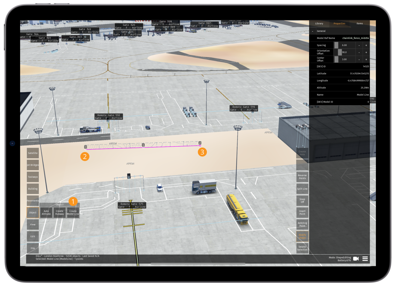
Object
| Button | Function |
|---|---|
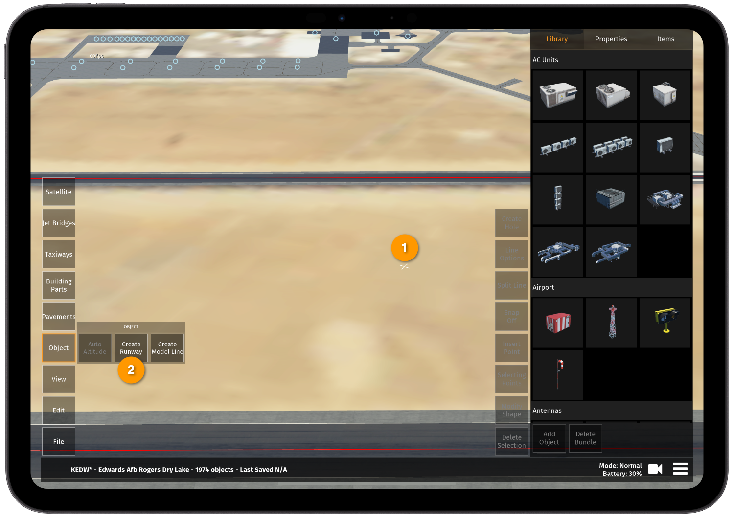
| Auto Altitude | Automatically adjusts the altitude of the selected building(s) and/or object(s) so that they sit on top of the building(s) that they are currently place within (or ground level if the building/object was set to a higher/lower altitude before and nothing else is around them) |
| Create Runway | Can be used to create a new runway if necessary - see 5.1 below |
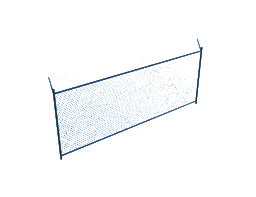
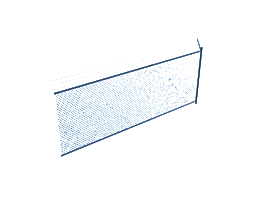
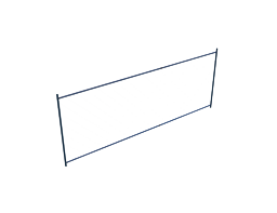
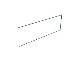
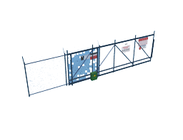
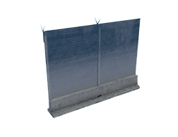
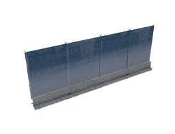
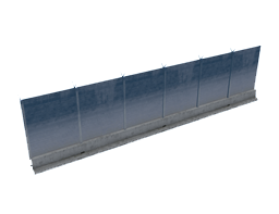
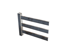
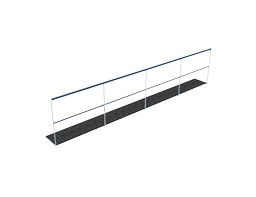
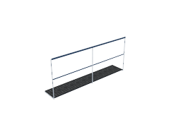
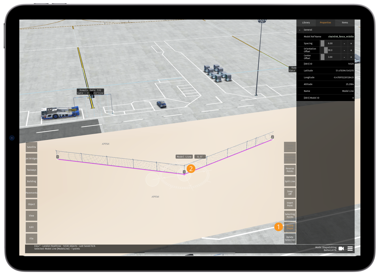
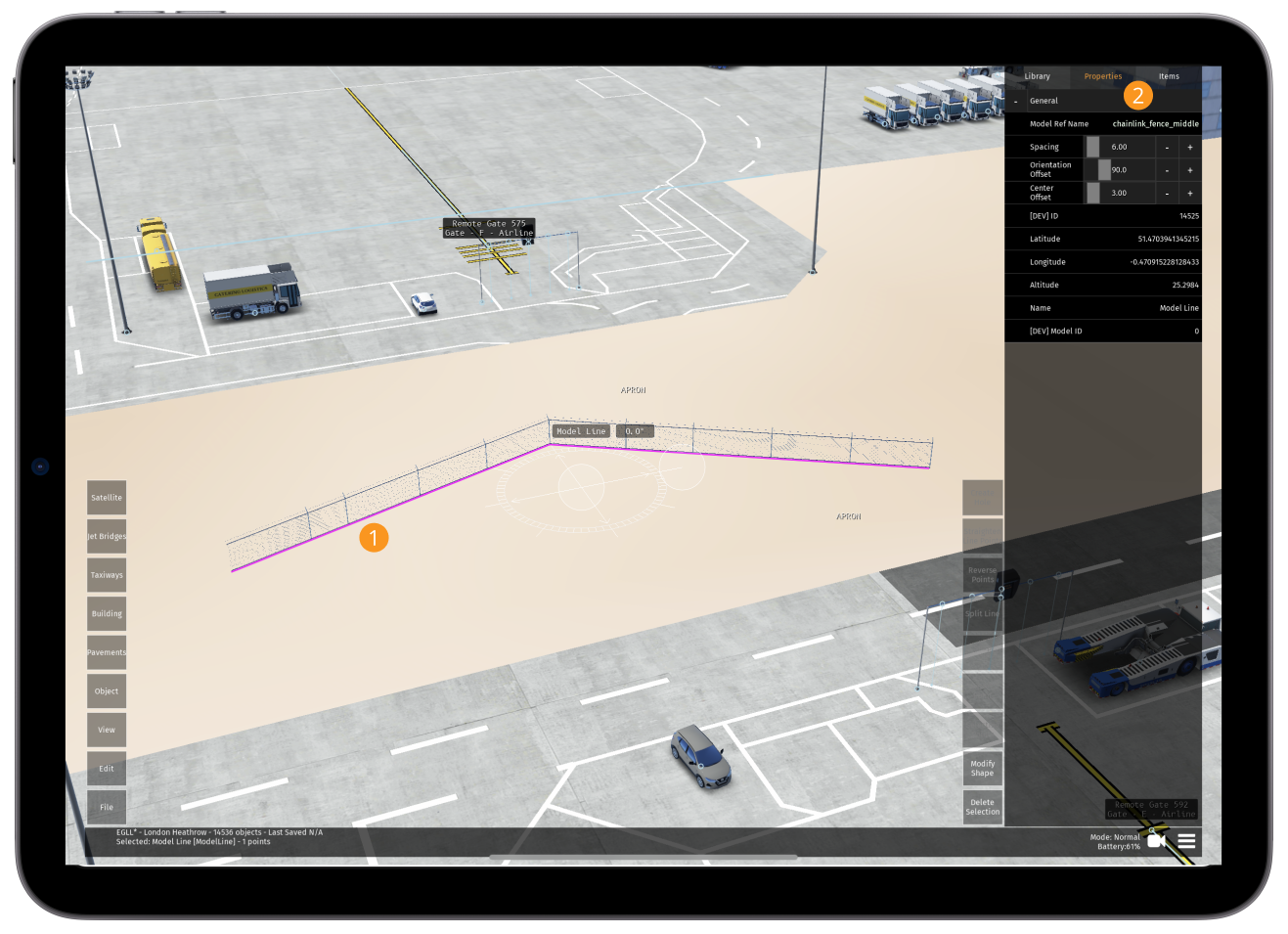
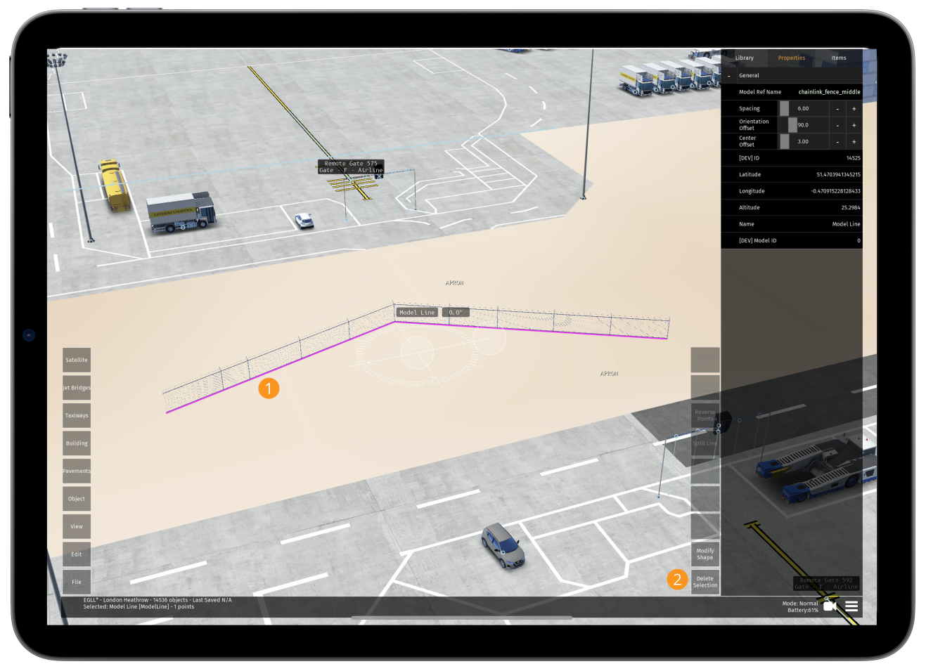
| Create Model Line | After tapping this button, tap in the area that you want the first edge of fencing to appear in. With every tap, a new point will be created, each point is automatically joined and this will create a series fences (this tool is currently only available for fences and similar objects - see 10.5 below) |
Pavements
| Button | Function |
|---|---|
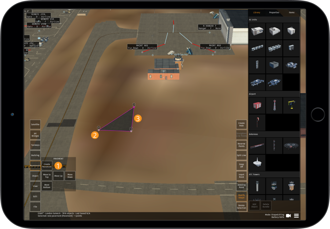
| Create Pavement | After tapping this button, tap in the area that you want the first edge of pavement to appear in. With every tap, a new point will be created, each point is automatically joined and this will create a section of pavement |
| Move to Top | Adjusts the order of rendering and moves the selected pavement to the top (also works for taxiway lines) |
| Move Up | Adjusts the order of rendering and moves the selected pavement up one (also works for taxiway lines) |
| Move Down | Adjusts the order of rendering and moves the selected pavement down one (also works for taxiway lines) |
| Move Bottom | Adjusts the order of rendering and moves the selected pavement to the bottom (also works for taxiway lines) |
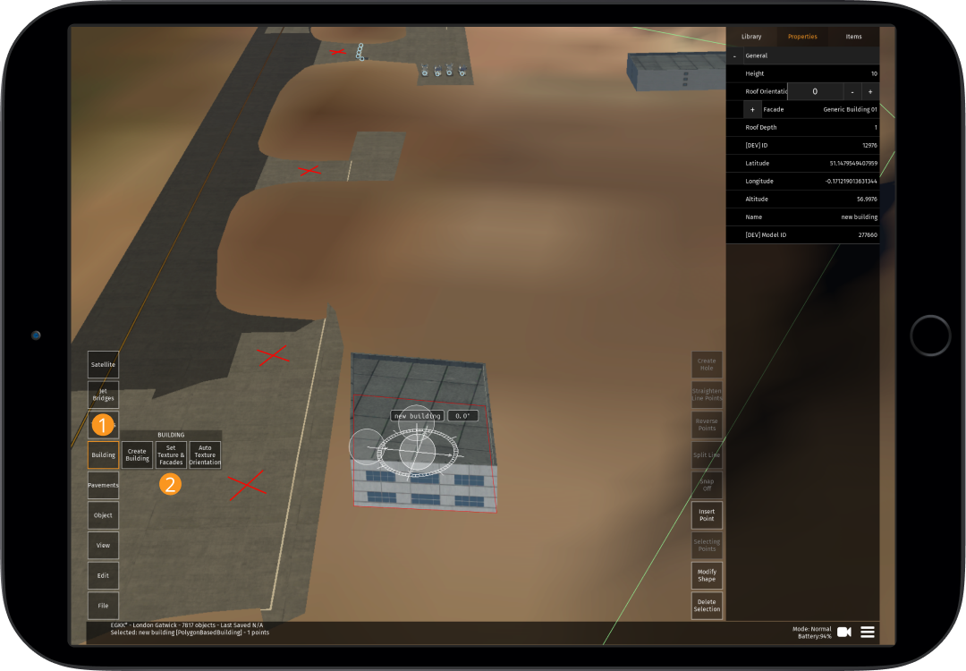
Building
| Button | Function |
|---|---|
| Create Building | After tapping this button, tap in the area that you want the first edge of building to appear in. With every tap, a new point will be created, each point is automatically joined and this will create a section of building |
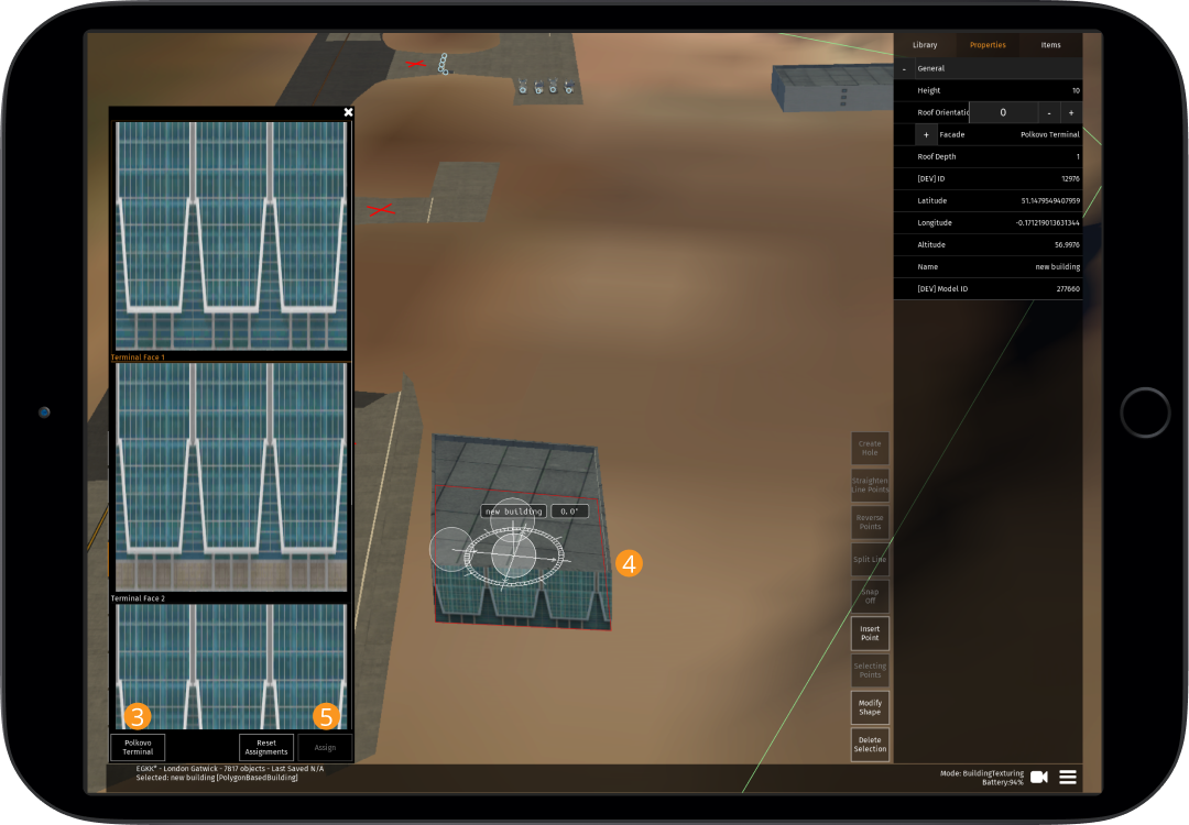
| Set Texture & Facades | Once a building is selected, facades can be selected and changed |
| Auto Texture Orientation | This will take the longest line of the building or pavement selected, and align the texture (roof pattern for buildings) to this line |
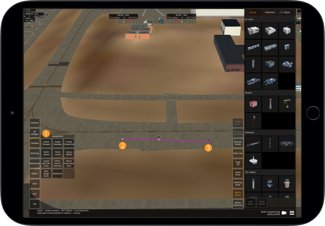
Taxiways
| Button | Function |
|---|---|
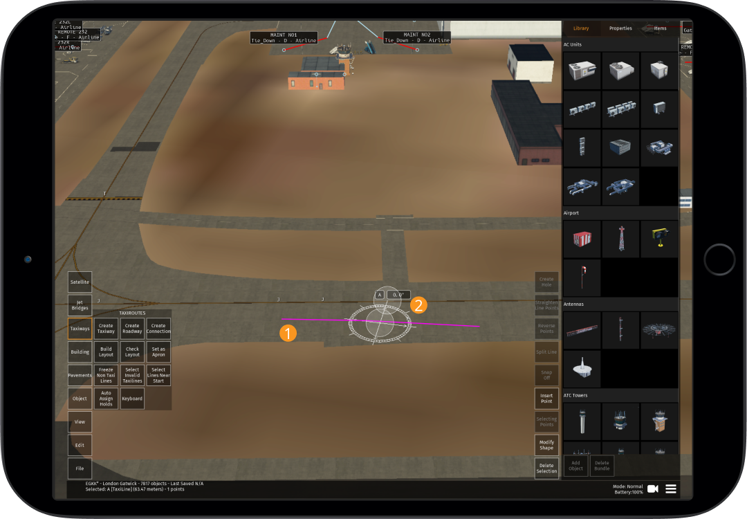
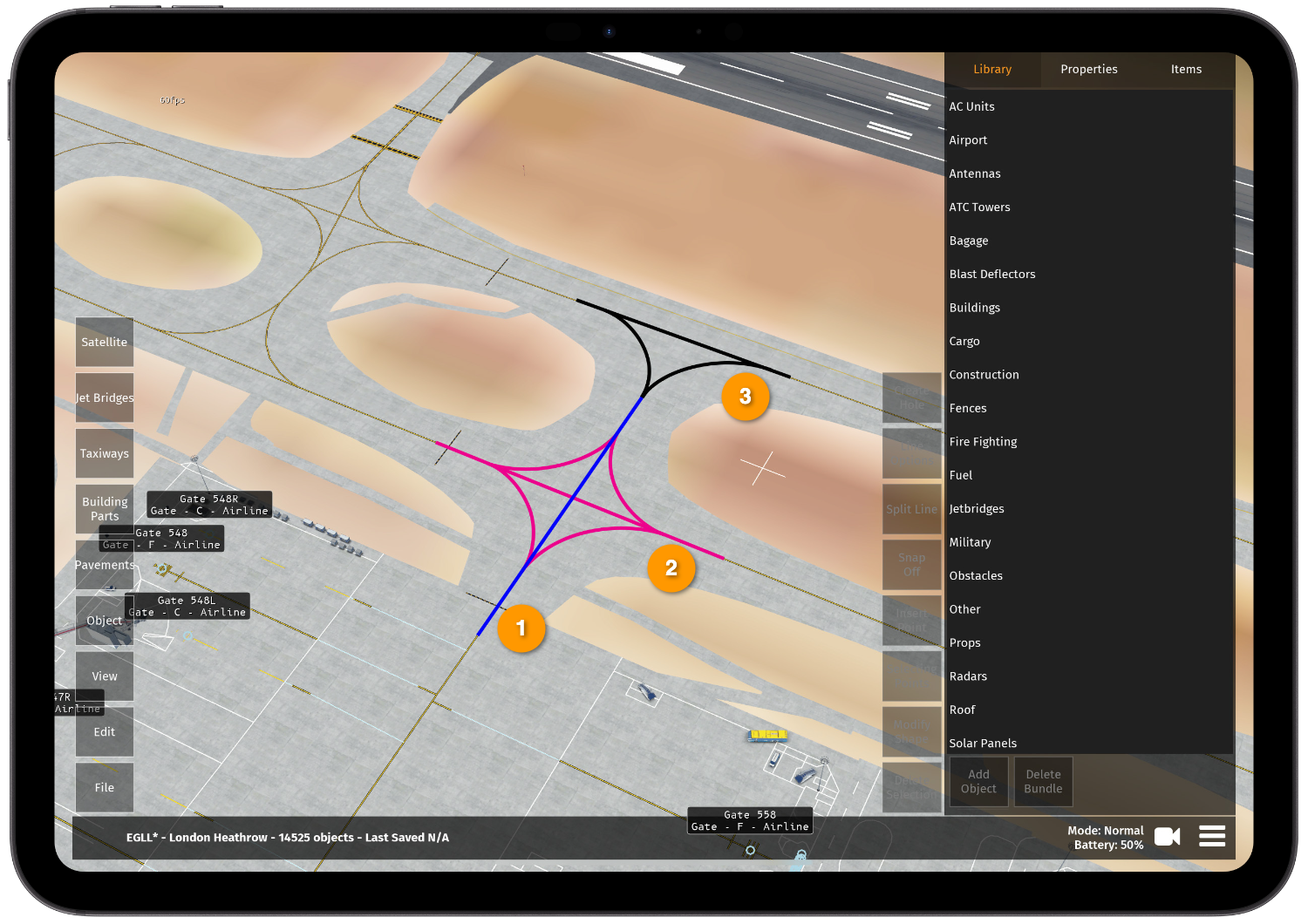
| Create Taxiway Line | After tapping this button, tap in the area that you want the first edge of taxiway line to appear in. With every tap, a new point will be created, each point is automatically joined and this will create a series of taxiway lines |
| Create Roadway Line | After tapping this button, tap the area that you want to have a roadway line. With every tap, a new point will be created, each point is automatically joined and this will create a series of roadway lines |
| Create Taxiway Connection | After tapping this button, tap the area that you want to have a taxiway connection. With every tap, a new point will be created, each point is automatically joined and this will create a series of taxiway connections |
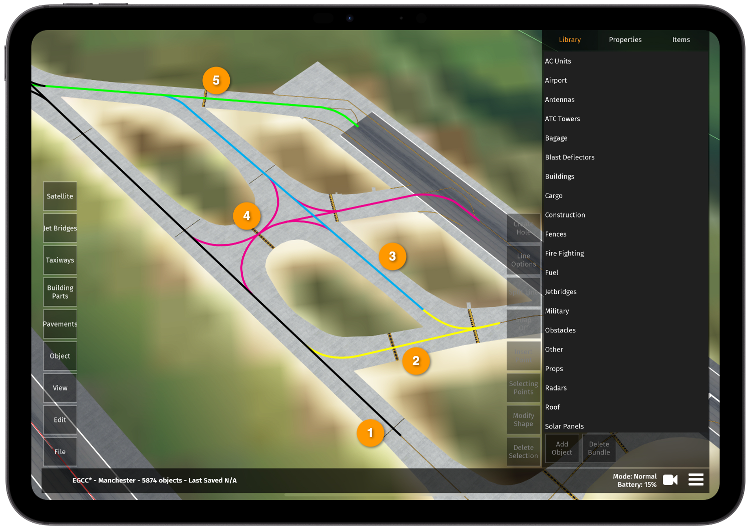
| Build Taxiway Layout | Tapping this button will mean that routes from each start location to the runway(s) can be checked. If any changes are made, this button needs to be re-tapped before you can "Check Taxiway Layout" again |
| Check Taxiway Layout | This button will check if the taxiway route from the start location to the runway(s) is valid. This is color coded and shown under each start location |
| Set as Apron | This will rename any taxiway(s) selected as APRON. This must be done for any taxiways that are not named on charts and for taxiway connections |
| Freeze Non Taxi Line | This is an editing mode for taxi lines that freezes all lines that do not have usage as "Aircraft" (recommended whenever working with taxi lines) |
| Select Invalid Taxi Lines | Once the taxi network has been completed, tap this button to see if any taxi lines have been missed. Any remaining taxi lines that are not part of the network are shown in magenta (regardless of zoom level) |
| Select Lines Near Start | Selects all lines near start spawn points so that they can be recategorised as non taxiway routable lines (these are the lines that are used for aircraft nose wheels to park on) |
The "Move to Top/Bottom" and "Move Up/Down" buttons within "Pavement" also work for taxiway lines
Satellite
| Button | Function |
|---|---|
| Import Imagery | Used to access pre-saved zipped KML files with satellite imagery for editing |
| Latitude Offset | Press, hold and then slide your finger up or down to adjust the latitude of the satellite imagery (this can be by between +/-0.01 and +/-2.00 meters) |
| Longitude Offset | Press, hold and then slide your finger up or down to adjust the longitude of the satellite imagery (this can be by between +/-0.01 and +/-2.00 meters) |
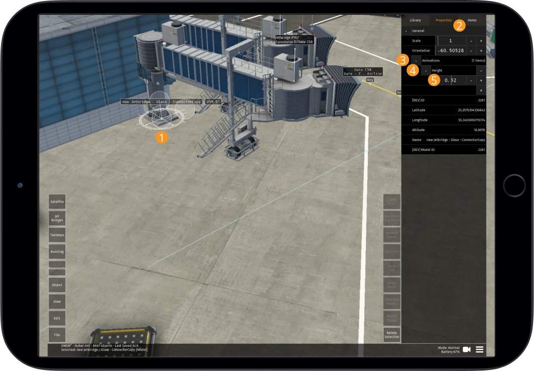
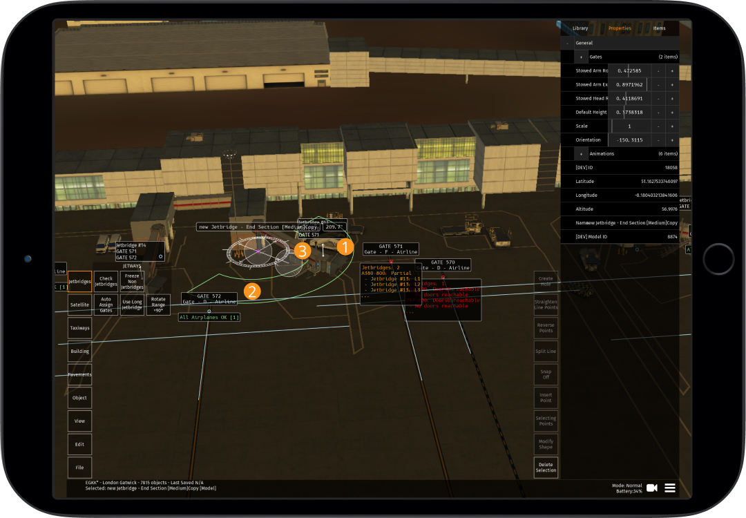
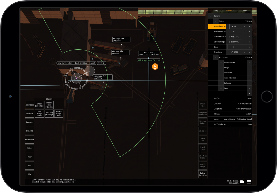
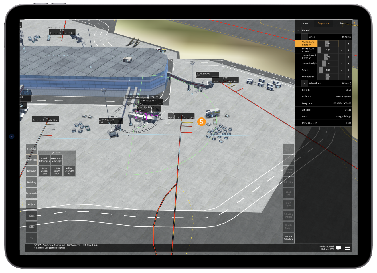
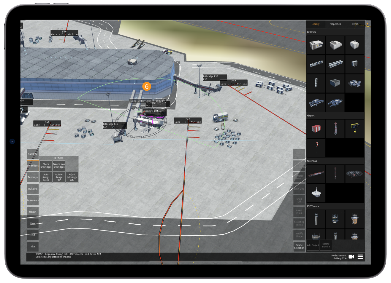
Jetbridges
| Button | Function |
|---|---|
| Check Jetbridges | Checks all start locations for errors such as jet bridges not reaching doors. These are color coded (see 11.4.1 below) |
| Freeze Non Jetbridges | This is an editing mode for jet bridges, only allowing the selection of jet bridge end sections and start locations (recommended whenever working with jet bridges) |
| Auto Assign Gates | Automatically assigns jet bridges to gates (see 11.4.4 below) |
| Rotate Range +90 degrees | Some jet bridges are positioned with an orientation that doesn’t allow animation to reach the doors. This button rotates the base position 90 degrees and sets the stowed angle of the jet bridge so it’s at the same position as before whilst allowing a wider range of rotation |
| Adjust Jet Bridge Alt | Adjusts the altitude of all elements of a jet bridge that are selected to the same altitude as the first selected part of the jet bridge (see 11.4.7 below) |
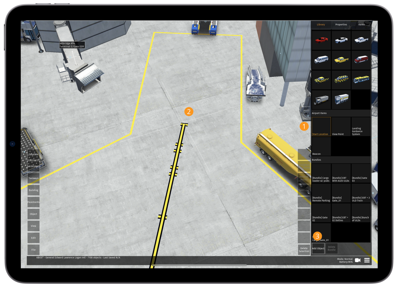
Navigation Bar
2.1.3
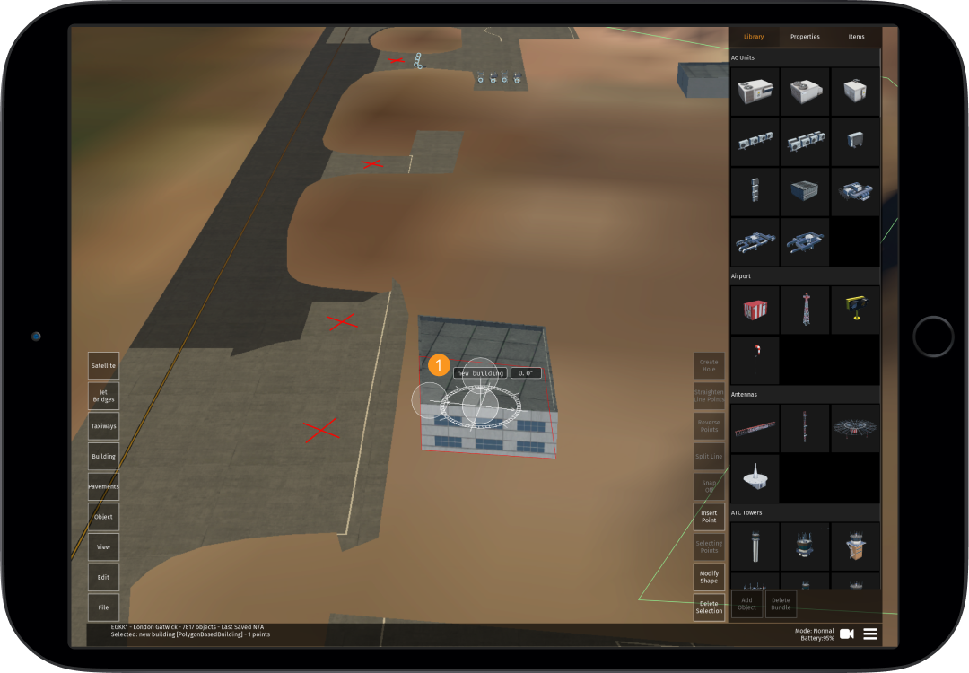
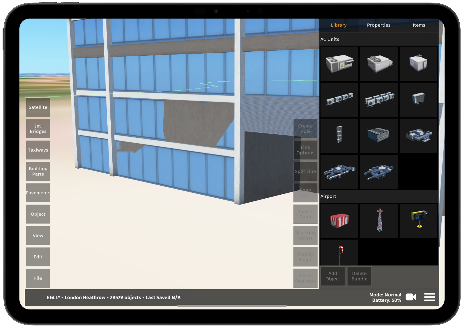
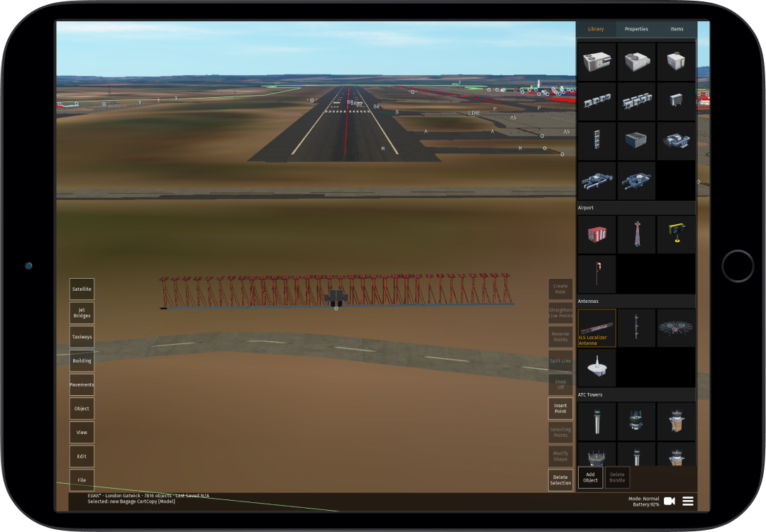
Library
This contains a repository of all available objects that can be used. How to add objects can be found later in this manual (see 10.2.2 below)
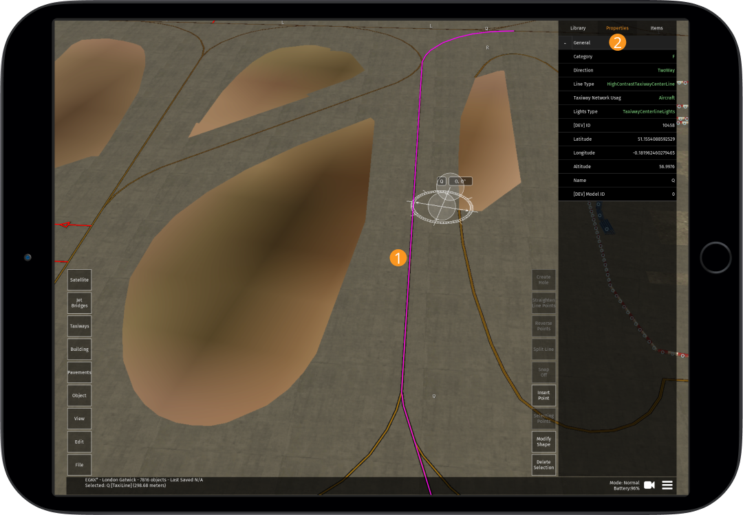
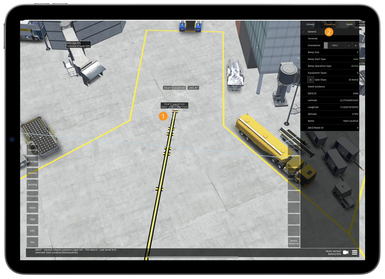
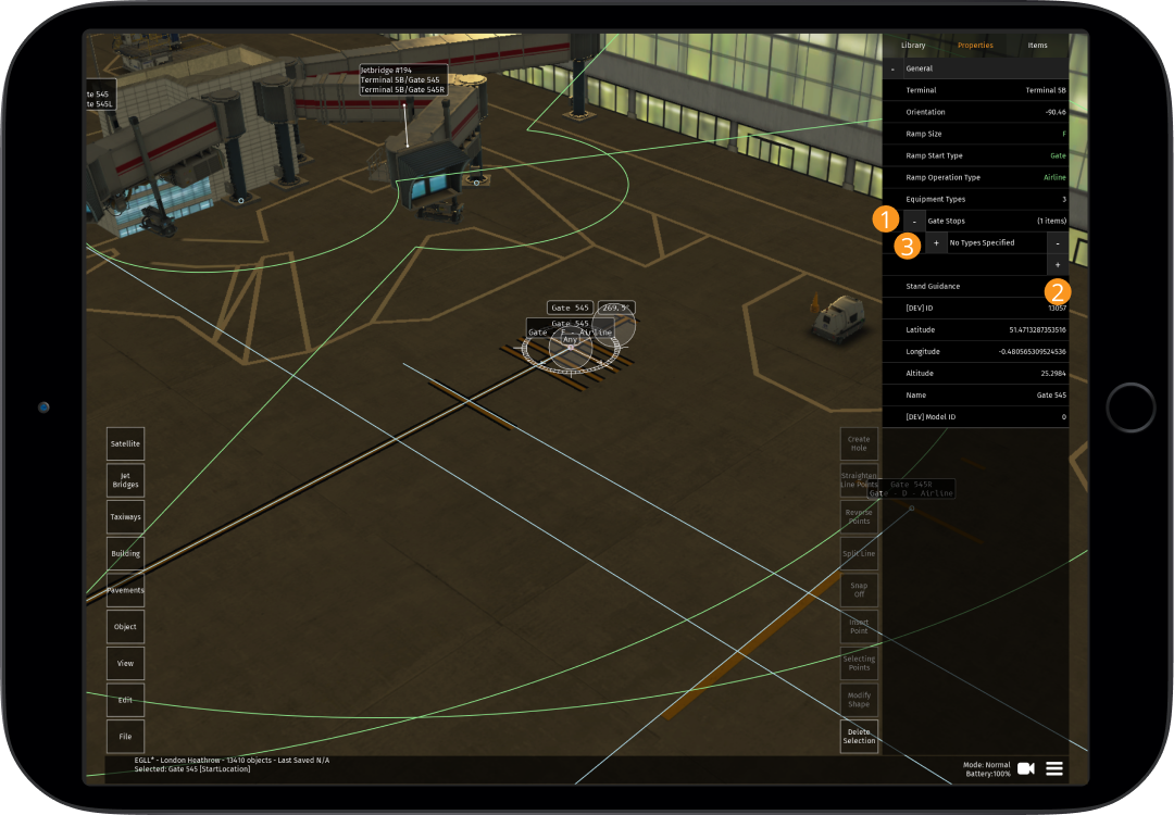
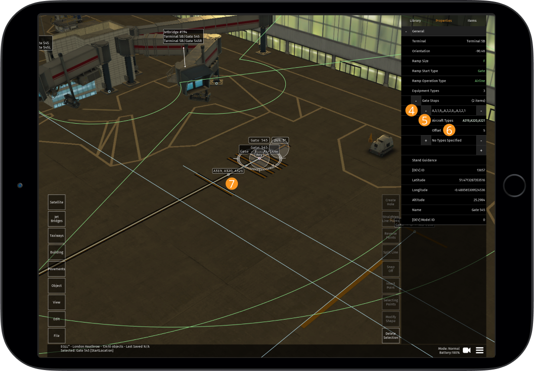
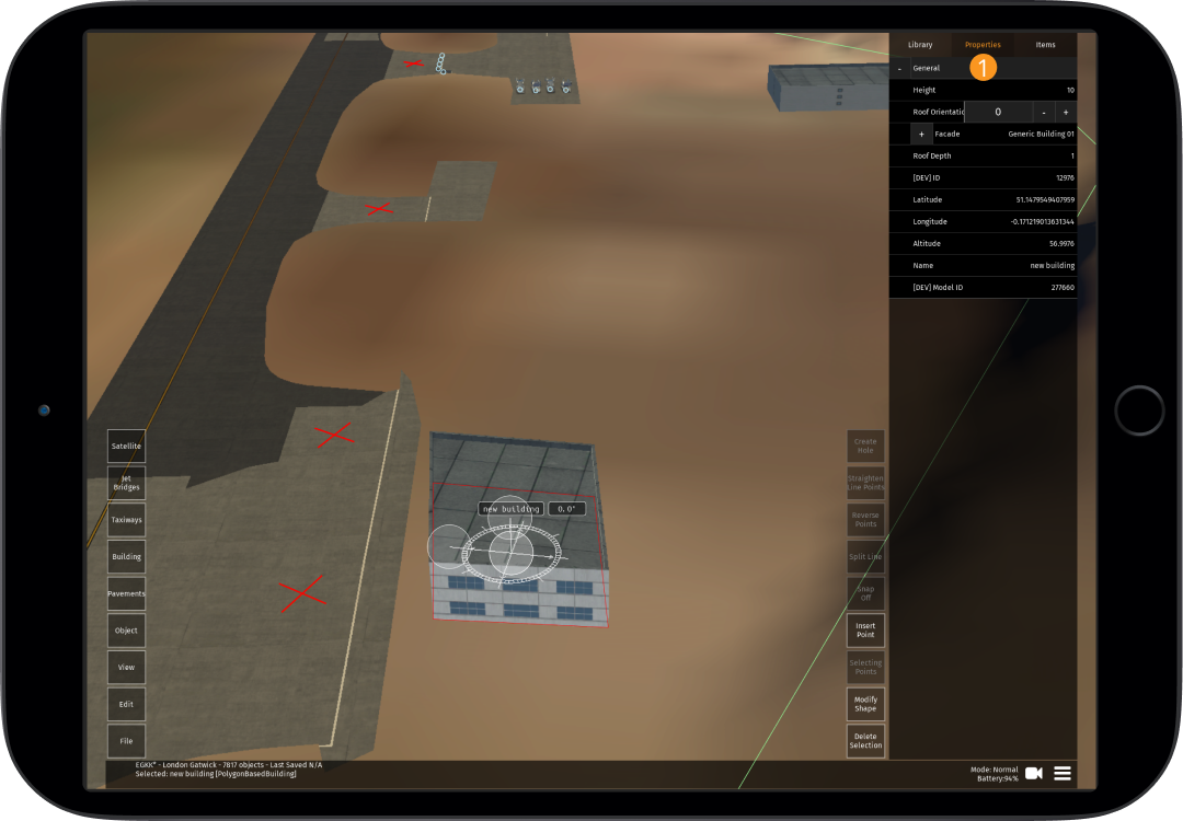
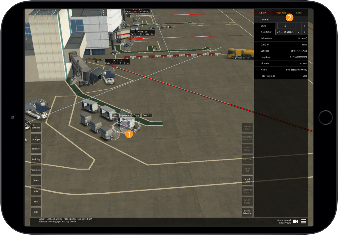
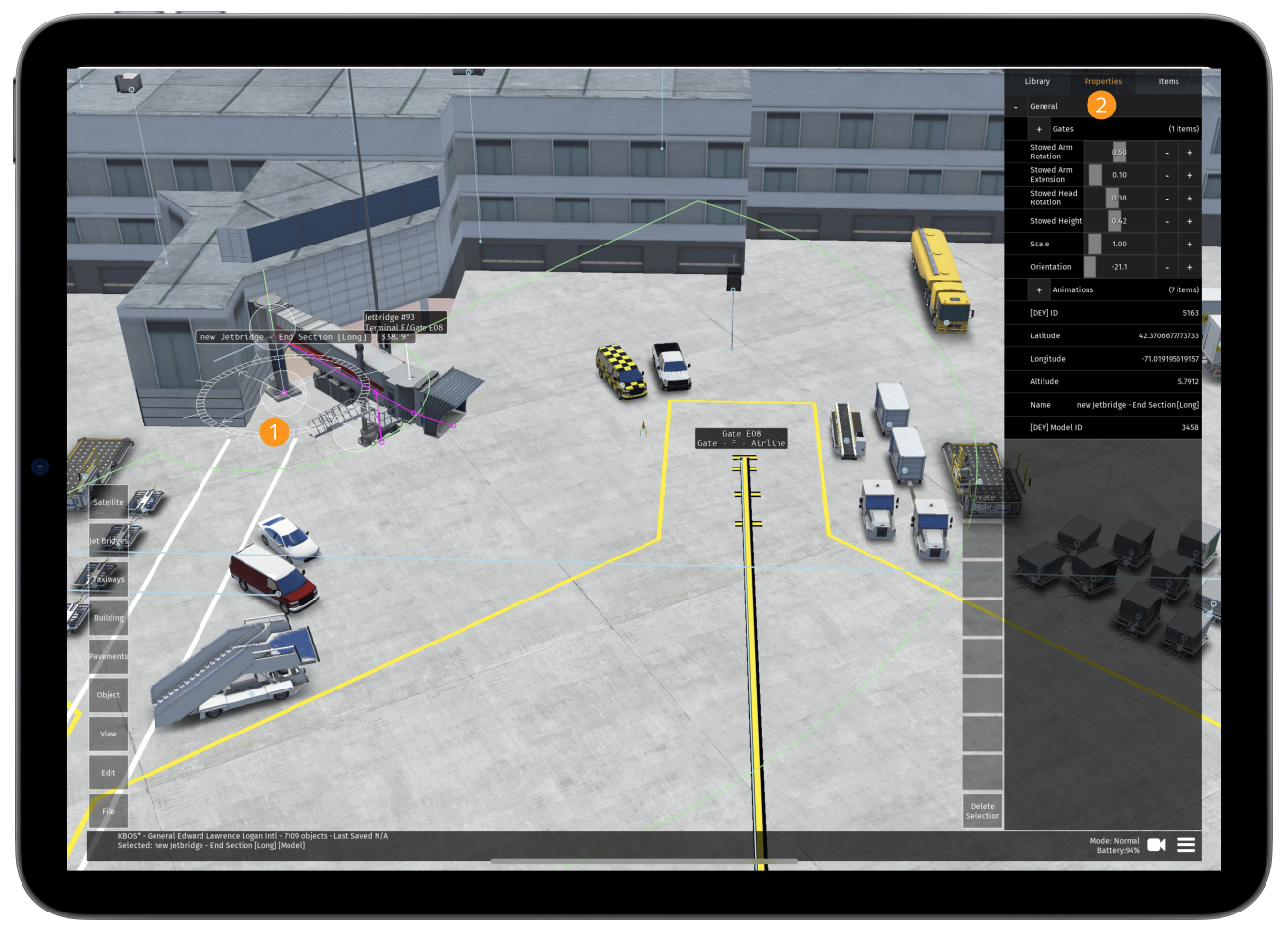
Properties
The properties tab will vary based on whether buildings, objects, start positions, lines, pavements or jet bridges are selected. They can all be changed from within this tab.
Items
This shows a list of all buildings, lines, pavements and objects that are currently loaded at the airport. You can scroll up/down using your finger.
Tapping on an item within the list will select the object and show the "changing orientation" movement symbols to make it easy to identify at your airport (see 10.2.3 below)
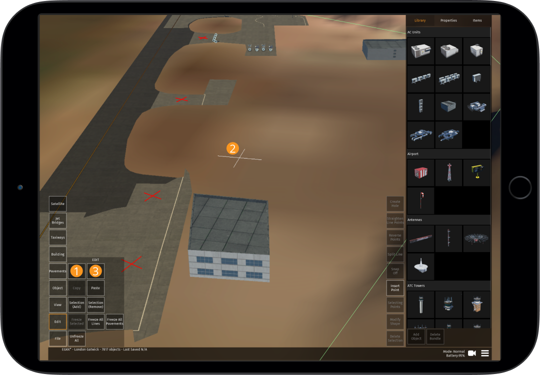
Edit Buttons
2.1.4
Edit
| Button | Function |
|---|---|
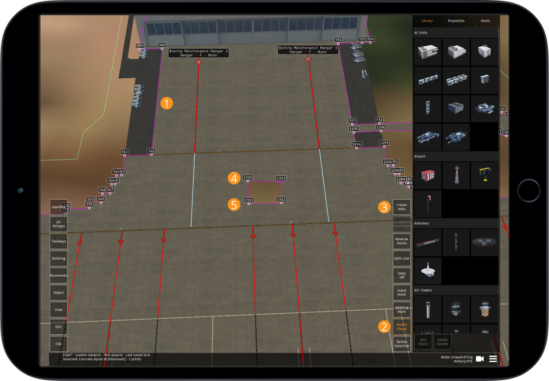
| Create Hole | With a section of pavement selected, this button will allow holes to be created within a block of pavement (see 6.1.5 below) |
| Line Options | Tapping on this will show to following options: Simplify - This will reduce the number of nodes required to form a line, useful for reducing nodes on taxiway curves with excessive nodes Reverse - All points are numbered, this button will reverse the numbering of all points (this can also be used for buildings that are "inside out") Straighten - Select a series of points and then tap this button to straighten the line between all points selected |
| Split Line | Select a line, and then a point within that line. You can then tap "Split Line" to split it into two separate lines (particularly useful for naming different taxiways that are currently all one line). The line after the point where the split was made will remain selected |
| Snap Off / Snap to All / Snap to Type | Snapping allows the Editor to "attach" a point to another point/line to avoid gaps and/or overlapping. Snapping must be used to connect buildings/lines/pavements. When "Snap Off" is selected, you will be unable to snap. When "Snap to All" is selected, it allows you to snap buildings/lines/pavements to each other. "Snap to Type" works the same but is only to the same type (e.g. line to line etc.) |
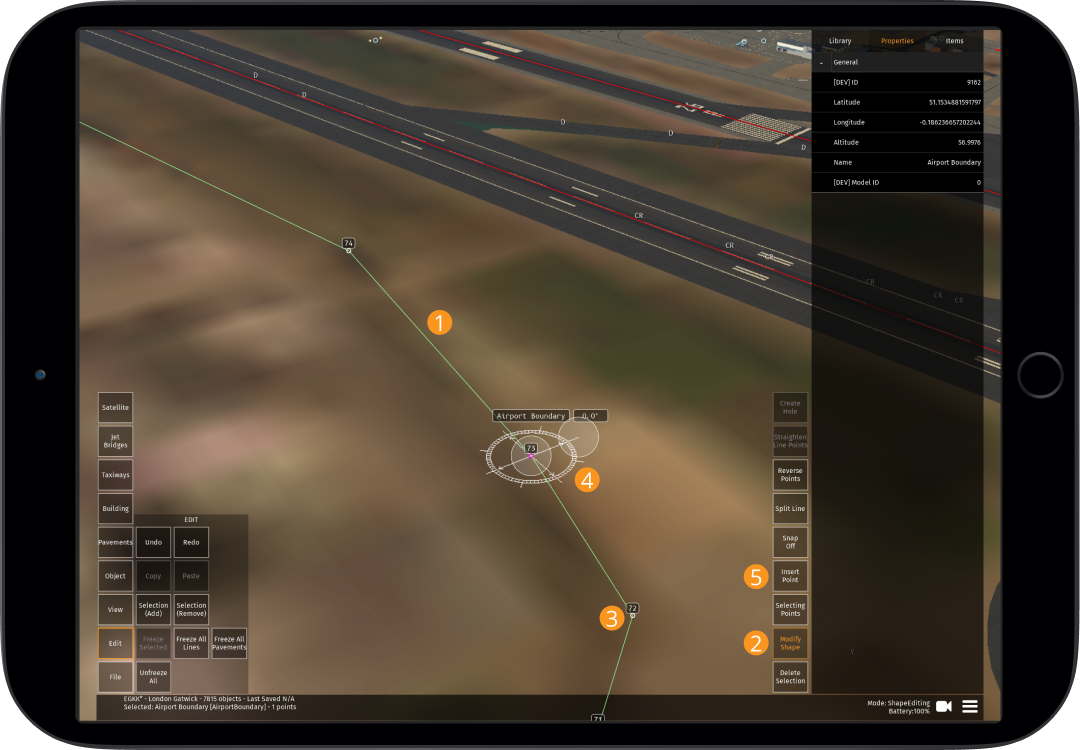
| Insert Point | This will insert a point with any building or pavement that is selected. This point will be added sequentially (i.e. after the last numbered point) unless a point within the line is selected, in which case a new point is created between this point and the next point |
| Adding/Selecting Point(s) | Tap this button to cycle between "Adding" and "Selecting". Adding Points will add a point between two points if the line/edge between them is tapped, or after the last numbered point if you tap anywhere else. Selecting Points will allow you to select a point (although you can still do this with "Adding Points" selected) |
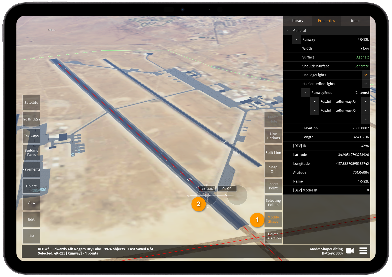
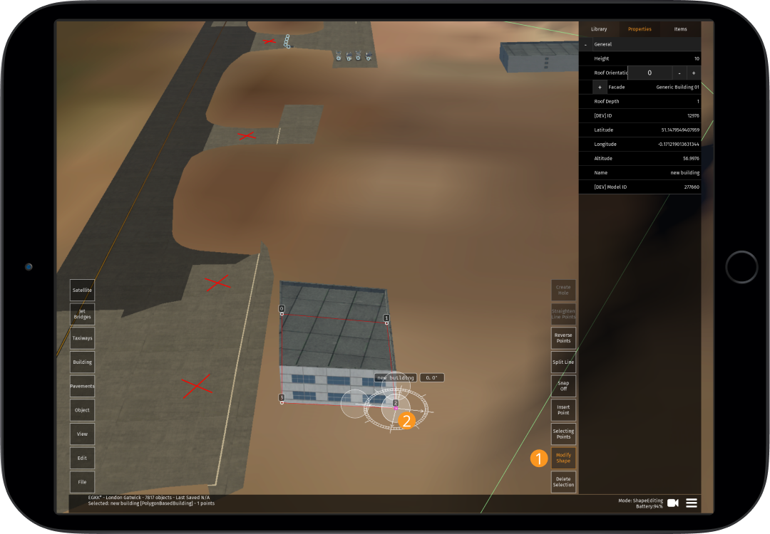
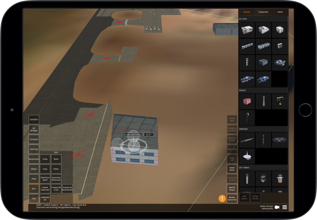
| Modify Shape | This must be tapped (amber when selected) to allow you to modify the shape of any building, taxiway point or pavement. When not selected you will only be able to move the entire shape rather than individual points |
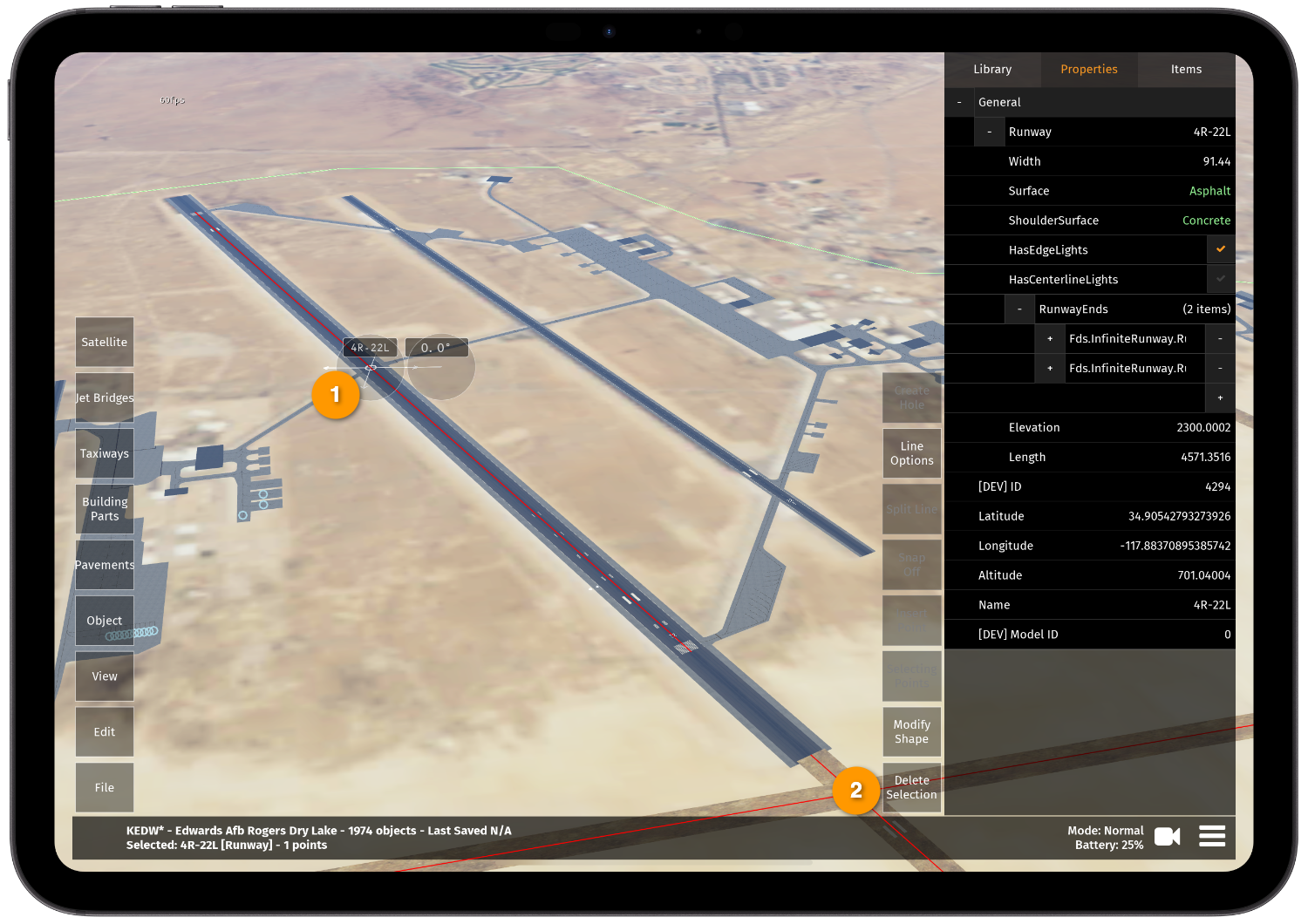
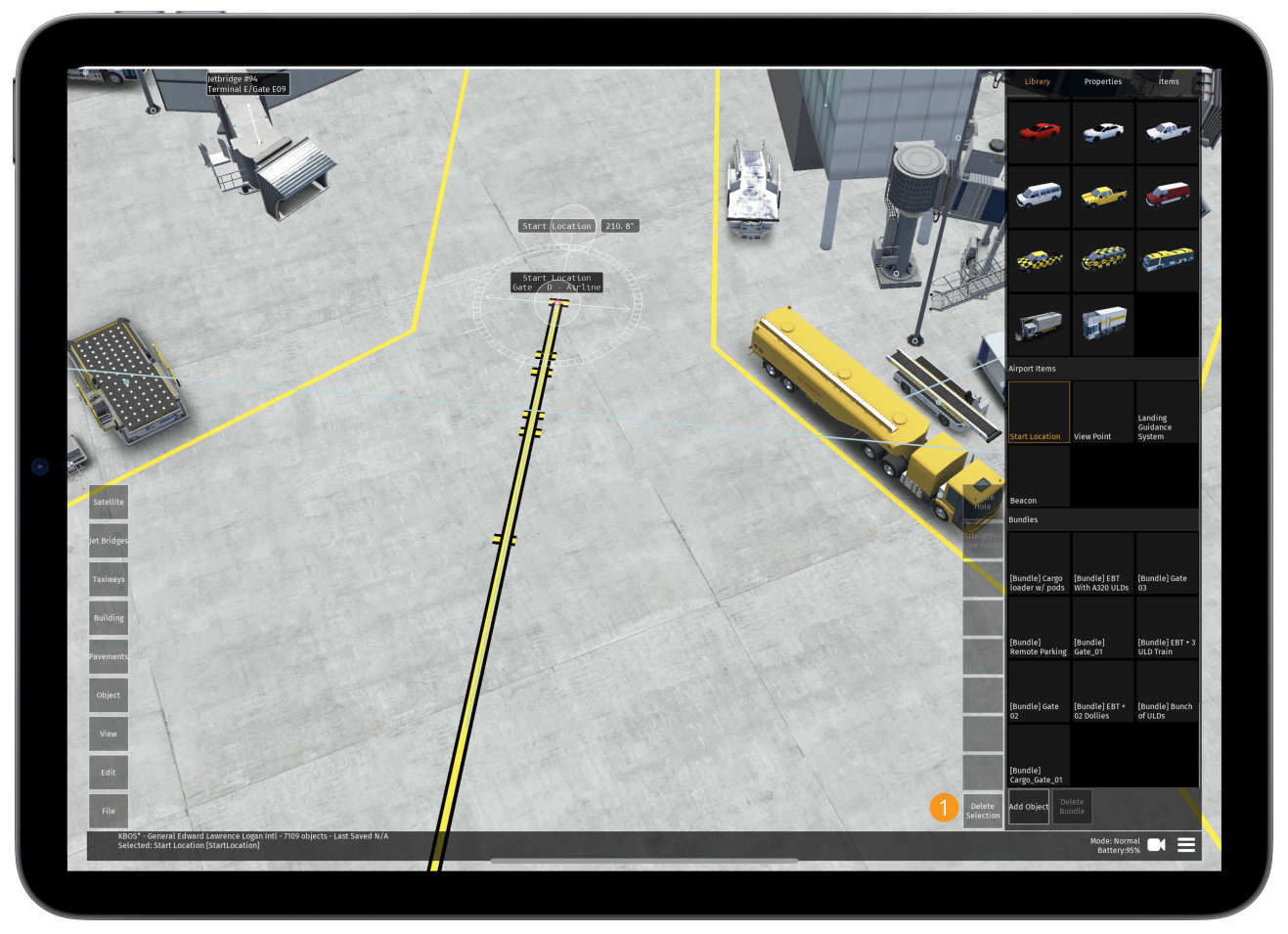
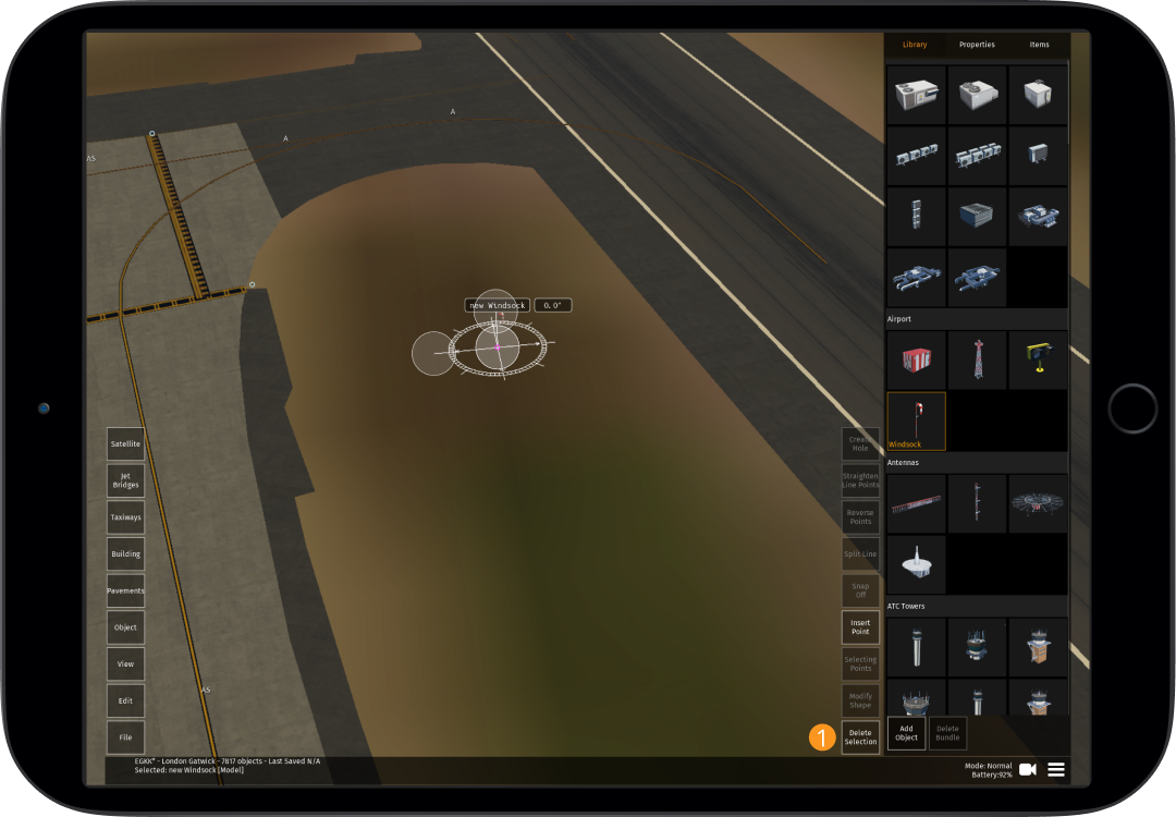
| Delete Selection | This button will delete the select buildings and objects |
Camera
2.1.5
-
Currently it is recommended to use the "Airport/Scen Editor" and "Birds Eye View" cameras when editing, however the "Free" camera is particularly useful for positioning the ATC Tower